Description
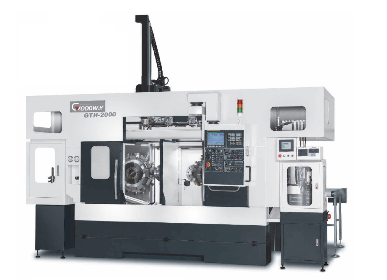
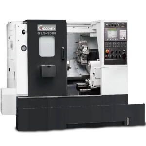
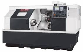
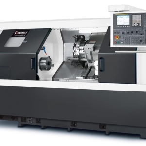
PARALLEL TWIN-SPINDLE CNC TURNING CENTER
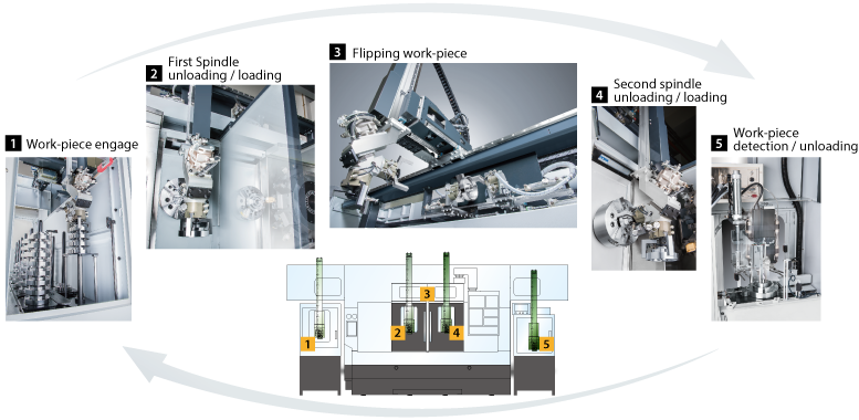
With leading technology and high quality components, the GTH series is particularly developed for automobile industry. By applying advanced parallel twin spindles, twin turrets structure and high efficiency automation system, the GTH provides automatic loading, front/rear cutting, unloading and work-piece detecting, which make its ultimate machining capabilities a coordinated process. Furthermore, the GTH series fulfills all types of plate-shape and short-shaft work-piece of automatic mass production needs.
Major structure adopts modular design which based on machining requirements, machine can be promoted to be an optimal production line, which highly reduces cost of manpower and increases production efficiency.
Parallel twin-spindle structure can reduce turret interference, which can fulfill precise machining accuracy of large plate-shape work-piece.
Z-axis traverse is designed as a combination of saddle and bed which its rigidity performs much better than quill type.
Live tooling turret and C-axis is available for option, which can achieve turning, milling and tapping on front and rear parts of work-piece in one machine as well as contour machining rear-end and cylinder surface.
HEAVY-DUTY CONSTRUCTION
By using Finite Element Analysis ( FEA ) and high tension Meehanite casting structure, super rigidity frame of spindles, turrets and saddle are reaching the optimal reinforcement. Mechanical strength is well enough to load extremely heavy cutting while maintaining long period of super high accuracy. Moreover, super rigidity of machine can extend life time of tools.
Parallel twin-spindle structure adopts modular isolating bed design which can efficiently decrease cutting resonance of two spindle systems and increase reliability of machining, roundness and roughness of appearance.
Major structural components of machine are united into one solid platform. The low center of gravity design provides firmly stable headstock and turret.
X / Z axes adopt super rigidity box ways design which is through heat treatment and precise finishing processes. And long span design of traverse can maximize strength and precision. Box way design also provides the rigidity needed for heavy-duty and interrupted turning applications.
Contact surfaces of all slides, headstock, turret, and ball screw bearing housings with the machine bed are precision hand scraped to provide maximum assembly precision, structural rigidity, and load distribution.


Z-axis super rigidity structure
Saddle features bed structure
Full travel of saddle and turret are firmly supported by bed, and distance of overhang of turret is shorter which increase cutting rigidity.
ULTIMATE MACHINING POWER
1. Head stocks feature even thickness sides, which evenly distribute cutting forces to the machine bed, resulting in exceptional vibration dampening characteristics and forms a stronger structure to handle interrupted and heavy cutting applications.
2. P4 grade ( Class 7 ) super-high precision bearings are directly assembled for maximum level of support and precision. Bearing configuration is designed for super heavy-duty cutting with ultra-smooth performance and long term durability with a higher level of accuracy.
3. Heat dispensing fins around the headstock evenly dispense heat to reduce deformation, therefore, increasing machining accuracy.


 Optional Pneumatic Work-Piece Positioning Detector
Apply pneumatic flow to detect work-piece and fit of clamping jaw surface. When not adjust closely to fit, robot arm will re-load again to ensure operation safety.
ADVANCED TURRET TECHNOLOGY
Heavy-duty servo indexing turret achieves 0.2 second indexing times for adjacent stations and 0.5 second times for stations at the opposite end of the disk turret.
Ø 210 mm ( 8.26″ ) diameter super high precision CURVIC couplings accurately position the turret disk ( ± 2 sec. of arc ) and 4,000 Kg ( 8818.48 lb ) of clamping force ensures abundant turret rigidity for all cutting conditions.
The CURVIC coupling is provided with automatic centering, cleaning and super large contact area of tooth flank, which ensures long-term usage of cutting rigidity and positioning accuracy.
The 12-station YAMA SEIKI live tooling turret offers 12 station available for live tooling ( live tooling tools rotate in working position only ) and features a non-lifting turret disk.
YAMA SEIKI’s live tooling turret utilizes advance servo indexing technology to achieve 0.2 second indexing times for adjacent stations and 0.5 second for stations at the opposite end of the disk.
With the latest technology, live tooling is driven by an AC servo motor to provide ample power, in the form of torque. Now, even the toughest of jobs may be tackled without a sweat.
ULTIMATE C-AXIS SPINDLE
Working with the live tooling turret, the Cf-axis and disk brake system enables the machine to perform multiple tasks, such as drilling, tapping, and milling operations, including cylindrical and polar coordinate interpolations, resembling a 4th-axis rotary table on a machining center.
With the FANUC servo motor generating an ultra high resolution of 33,000,000 pulses per spindle rotation and 480 Nm ( 354 ft-lb ) of spindle torque ( Cont. ), machined surface finishes are much superior than Cs-axis ( driven by spindle motor ) equipped machines. Plus, dynamic accuracy is within ± 0.02° even under heavy cutting loads.
AUTOMATIC PRODUCTION SYSTEM
Depend on different work-piece specifications and machining characteristics, YAMA SEIKI provides elastic configurations of automatic production system to ensure operation needs of high efficiency and unmanned machinery space.
X-axis Rapids : 2,500 mm/sec. ( 98.42 inch/sec. )


Rotary Twin Jaws Robot Arm
Feature pneumatic work-piece positioning detector, unloading, positioning detector, loading can be done in one setup which is pretty safe and quick.
Work-piece Detecting System
Depend on actual needs to setup accuracy condition, qualified and unqualified products will be automatically distinguished, which efficiently saves manpower.

| Gantry type loading / unloading system | ||
|---|---|---|
| Loader work-piece handling capacity ( weight ) |
3 Kg ( 6.6 lb ) x2 | |
| Loader work-piece handling capacity ( size ) |
Ø 150 x 80 mm ( Ø 5.9″ x 3.15″ ) |
|
| X-axis ( Left / Right ) | Stroke | 4,200 mm ( 165″ )*1 |
| Max. speed | 2,500 mm/sec. ( 98.42 inch/sec. ) |
|
| Y-axis ( Up / Down ) | Stroke | 800 mm ( 31.49″ ) |
| Max. speed | 2,000 mm/sec. ( 78.7 inch/sec. ) |
|
| Z-axis ( Front / Rear ) | Stroke | 210 mm ( 8.26″ ) |
| Max. speed | 500 mm/sec. ( 19.68 inch/sec. ) |
|
| C -axis | Stroke | 180˚ |
| Max. speed | 1 sec/180˚ | |
*1 Stroke varies from requirements.





Reviews
There are no reviews yet.