


-

Features & Benefits
Reduced cycle times
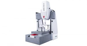
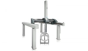
Leitz Reference BX combines an integrated rotary table, multisensor capability, and automated sensor exchange to save time by increasing accessibility to a part’s surface and removing the delays of manual probe changes. The machine’s cutting-edge technology can reduce cycle times by up to 50%.Maximum accuracy
The Precitec S3 optical sensor offers ultra-precise non-contact measurement ideal for reflective and curved surfaces and sensitive material or very demanding new materials like carbon fibre composites. The tactile HP-S-X1C scanning probe is idea for inspecting surfaces with the tightest of tolerances and offers excellent feature accessibility with extension lengths ranging from 20 to 225 mm.Complete Part Accessibility
The combination of a rotary Table, horizontally fixed sensors and SENMATION allow the user to inspect the entire part faster without having to stop between part set-ups or probe changes. -

Technical Data
CMM Specifications and Gear InspectionCMM Specifications
Model X stroke [in] Y stroke [in] Z stroke [in] 5.4.3 19.685″ 15.748″ 11.811″ 7.7.5 27.5591″ 27.5591″ 19.685″ 10.7.6 3.93701″ 27.5591″ 22.8346″ 12.9.7 47.24409″ 35.4331″ 27.1654″ 15.9.7 59.05512″ 35.4331″ 26.378″ 20.9.7 78.74016″ 35.4331″ 27.1654″ 15.12.10 59.05512″ 47.24409″ 39.3701″ 22.12.10 86.61417″ 47.24409″ 39.3701″ 30.12.10 118.1102″ 47.24409″ 39.3701″ 40.12.10 177.1654″ 47.24409″ 39.3701″ 45.12.10 177.1654″ 47.24409″ 39.3701″ 30.15.10 118.1102″ 59.05512″ 39.3701″ 26.15.14 102.3622″ 59.05512″ 53.14961″ 33.15.14 129.9213″ 59.05512″ 53.14961″ Cylindrical gears:
- Spur, helical, double helical, splines (internal and external)
- Clutch gears (internal and external)
- Gear segments (minimum no. of teeth: 1)
- Gear racks
Bevel gears:
- Straight bevel, spiral bevel, hypoid bevel, crown gears
Curvic Couplings
Gear cutting tools:
- Hob cutter, broach, shaper cutter, shaving gears, form cutter
Available interfaces:
- Gleason GAGE 4/WIN; Klingelnberg KIMOS, DMG, Depo
Evaluation standards:
- DIN, ISO, AGMA, ANSI, JIS, CNOMO, CAT
-
Technical Data
CMM Specifications
Model X stroke [in] Y stroke [in] Z stroke [in] 5.4.3 19.685″ 15.748″ 11.811″ 7.7.5 27.5591″ 27.5591″ 19.685″ 10.7.6 3.93701″ 27.5591″ 23.2283″ 12.9.7 47.24409″ 35.4331″ 27.5591″ 15.9.7 59.05512″ 35.4331″ 26.7717″ 20.9.7 78.74016″ 35.4331″ 27.5591″ 15.12.9 59.05512 47.24409″ 35.4331″ 22.12.9 86.61417″ 47.24409″ 35.4331″ 30.12.9 118.1102″ 47.24409″ 35.4331″ 40.12.9 177.1654″ 47.24409″ 35.4331″ 45.12.9 177.1654″ 47.24409″ 35.4331″ 30.15.9 118.1102″ 59.05512″ 35.4331″ Gear InspectionCylindrical gears:
- Spur, helical, double helical, splines (internal and external)
- Clutch gears (internal and external)
- Gear segments (minimum no. of teeth: 1)
- Gear racks
Bevel gears:
- Straight bevel, spiral bevel, hypoid bevel, crown gears
Curving Couplings
Gear cutting tools:
- Straight bevel, spiral bevel, hypoid bevel, crown gears
Available interfaces:
- Gleason GAGE 4/WIN; Klingelnberg KIMOS, DMG, Depo
Evaluation standards:
- DIN, ISO, AGMA, ANSI, JIS, CNOMO, CAT
-
CMM Specifications
Model X stroke
[in]Y stroke
[in]Z stroke
[in]Infinity 12.10.7 47.24409″ 39.3701″ 27.5591″ Max table load: 750kg.
Applications
Cylindrical gears:
- Spur, helical, double helical, splines (internal and external)
- Clutch gears (internal and external)
- Gear segments (minimum No. of teeth: one)
- Gear racks
Bevel gears:
- Straight bevel, spiral bevel, hypoid bevel, crown gears
- Gleason GAGE 4/WIN; Klingelnberg KIMOS; DMG
Gear cutting tools:
- Hob cutter, broach, shaper cutter, shaving gears, form cutter
Evaluation standards:
- DIN, ISO, AGMA, ANSI, JIS, CNOMO, CAT
Max. gear weight 750 kg
Module range 0.019685″ – 3.93701″
Max. gear width 27.5591″
Max. shaft length 47.24409″
Max. gear diameter Spur gears: 37.4016″
helical gears: 27.5590551″ (depending on module and styli configuration) -
CMM Specifications
Model X stroke
[in]Y stroke
[in]Z stroke
[in]8.10.6 31.4961″ 39.3701″ 22.6378″ 12.10.6 47.24409″ 39.3701″ 22.6378″ 12.10.7 47.24409″ 39.3701″ 22.6378″ 16.12.7 62.99213″ 47.24409″ 27.5591″ 24.12.7 94.48819″ 47.24409″ 27.5591″ 24.16.7 94.48819″ 62.99213″ 27.5591″ 16.12.10 62.99213″ 47.24409″ 39.3701″ 24.12.10 94.48819″ 47.24409″ 39.3701″ 24.16.10 94.48819″ 62.99213″ 39.3701″ Applications
Cylindrical gears- Spur, helical, double helical, splines (internal and external)
- Clutch gears (internal and external)
- Gear segments (minimum no. of teeth: one)
- Gear racks
Bevel gears
- Straight bevel, spiral bevel, hypoid bevel, crown gears
- Interfaces: Gleason GAGE 4/WIN; Klingelnberg KIMOS, DMG
Gear cutting tools
- Hob cutter, broach, shaper cutter, shaving gears, form cutter
Evaluation standards:
- DIN, ISO, AGMA, ANSI, JIS, CNOMO, CAT
Gear inspection with
Leitz PMM-Xi
Related SpecificationsPMM-Xi 8.10.6 PMM-Xi 12.10.6
12.10.7PMM-Xi 16.12.7
24.12.7PMM-Xi 16.12.10
24.12.10PMM-Xi 24.16.7
24.16.10Modul range [in] 0.019685″ – 3.93701″ (smaller modules on request) Max. gear diam. – spur [in] 29.5276″ 37.4016″ 45.27559″ 45.27559″ 61.02362″ Max. gear diam. – helical* [in] 19.685″ 27.5591″ 35.4331″ 35.4331″ 51.1811″ Max. gear width [in] 22.6378″ 27.5591″ 27.5591″ 39.3701″ 27.5591″ / 39.3701″ Max. shaft length [in] 39.3701″ 47.24409″ 62.99213″ / 94.48819″ 62.99213″ / 94.48819″ 94.48819″ * Depending on styli configuration and module
-
CMM Specifications
Model X stroke
[mm]Y stroke
[mm]Z stroke
[mm]8.10.6 800 1000 575 12.10.6 1200 1000 575 12.10.7 1200 1000 700 16.12.7 1600 1200 700 24.12.7 2400 1200 700 24.16.7 2400 1600 700 16.12.10 1600 1200 1000 24.12.10 2400 1600 1000 24.16.10 2400 1600 1000 Applications
Cylindrical gears:
- Spur, helical, double helical, splines (internal and external)
- Clutch gears (internal and external)
- Gear segments (minimum No. of teeth: 1)
- Gear racks
Bevel gears:
- Straight bevel, spiral bevel, hypoid bevel, crown gears
- Interfaces: Gleason GAGE 4/WIN; Klingelnberg KIMOS, DMG
Gear cutting tool:
- Hob cutter, broach, shaper cutter, shaving gears, form cutter
Evaluation standards:
- DIN, ISO, AGMA, ANSI, JIS, CNOMO, CAT
Gear inspection with
Leitz PMM-C
Related SpecificationsPMM-C 8.10.6 PMM-C 12.10.6
12.10.7PMM-C 16.12.7
24.12.7PMM-C 16.12.10
24.12.10PMM-C 24.16.7
24.16.10Module range [mm] 0.5 – 100 (smaller modules on request) Max. gear diam. – spur [mm] 750 950 1150 1150 1550 Max. gear diam. – helical* [mm] 500 700 900 900 1300 Max. gear width [mm] 575 575/700 700 1000 700 / 1000 Max. shaft length [mm] 1000 1200 1600 / 2400 1600 / 2400 2400 * Depending on styli configuration and module
-
CMM Specifications and Gear Inspection
Temperature range 18°C – 22°CModell X stroke
[mm]Y stroke
[mm]Z stroke
[mm]30.20.10 3000 2000 1000 30.20.16 3000 2000 1600 Temperature range 18°C – 24°C
Modell X stroke
[mm]Y stroke
[mm]Z stroke
[mm]30.20.10 3000 2000 1000 30.20.16 3000 2000 1600 Gear Inspection
Cylindrical gears:
- Spur, helical, double helical, splines (internal and external)
- Clutch gears (internal and external)
- Gear segments (minimum No. of teeth: 1)
- Gear racks
Bevel gears:
- Straight bevel, spiral bevel, hypoid bevel, crown gears
Available interfaces:
- Gleason GAGE 4/WIN; Klingelnberg KIMOS; bevel-gear-chain from University of Aachen, Depo
Gear cutting tools:
- Hob cutter, broach, shaper cutter, shaving gear, form cutter
Evaluation standards:
- DIN, ISO, AGMA, ANSI, JIS, CNOMO, CAT
Leitz PMM-F gear inspection systems – Related specifications PMM-F 30.20.10 PMM-F 30.20.16 Modul range [mm] 0,5 – 100 0,5 – 100 Max. gear dia. – spur [mm] 1950 1950 Max. gear dia. – helical* [mm] 1600 1600 Max. shaft length [mm] 3000 3000 *The max. gear diameter depends on modul and styli configuration.
-
Specifications
Measuring Range (in mm)
X Y Z 4000 – 5000 – 6000 5100 – 6300 – 8000 – 10000 2500 – 3000 – 3500 – 4000 Accuracy: MPEE = from 5.5 + 6 L/1000 < 30 -
Specifications
Measuring Range (in mm) X Y Z 2500 – 3000 – 3500 – 4000 3300 – 5100 – 6300 – 8000 2000 – 2500 – 3000 Accuracy (µm):MPEE= from 3.8 + 3.5 L/1000 -
Specifications
Measuring Range (in mm) X Y Z 2000 – 2500 3300 – 5000 1000 – 1500 – 1800 Accuracy: MPEE= from 3.5 + 3.5 L/1000 -
Specifications
Model X stroke
[mm]Y stroke
[mm]Z stroke
[mm]Accuracy [µm] 20.33.15 2000 3300 1500 MPEE= from 12 + 18 L/1000 20.40.15 2000 4000 1500 MPEE= from 12 +18 L/1000 20.33.18 2000 3300 1800 MPEE= from 12 +20 L/1000 20.40.18 2000 4000 1800 MPEE= from 12 + 20 L/1000 -
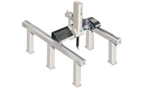
Designed for Stability
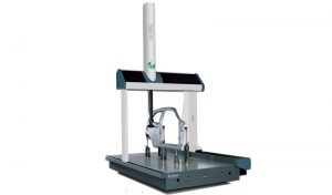
When purchasing a coordinate measuring machine, manufacturers need to be confident that their system will last for the long term. The all-aluminium ultra-rigid frame of the GLOBAL Advantage provides optimum stiff-to-mass ratio for unquestioned precision and long-term stability.Versatile Sensor Configuration
When creating an inspection plan for parts varying in complexity, feature characteristics and material types, manufacturers require a solution that is both precise and versatile. The GLOBAL Advantage CMM supports multisensor technology in a variety of configurations to suit different material types and feature characteristics. Whether you are looking for a more precise fixed probe head such as the HP-S-X5-HD or use an indexable probe head such as the HH-A 2.5 HD to reach more positions on the part, the GLOBAL Advantage can efficiently address the challenges. For even more access to hard-to-reach features, both probe head configurations are compatible with extension probes ranging from 750 mm up to 800 mm.Integration-Ready
Purchasing a CMM is an investment and manufacturers need to be prepared for the future. The GLOBAL Advantage CMM is accessible from four sides to ensure easy integrability with part loading/unloading systems. Furthermore, the system can be integrated with an automated loading/unloading system or supplied with specific fixturing, ensuring you are prepared for what lies ahead.Take the PULSE of Your Environment
Running part programs on large complex components take time. Having control of the environment surrounding your CMM during the entire measurement cycle is essential to obtain accurate measurement results the first time, every time. With added protection from pollution and dust, advanced temperature compensation algorithms and an optional environmental monitoring system, the GLOBAL Advantage CMM gives manufacturers confidence that their system is in optimal performance.Use Software to Embed Quality Across the Organisation
The right metrology software gives manufacturers the tools necessary to easily create and execute measurement routines and communicate the results quickly and effectively. PC-DMIS has over 20 years of built-in expertise enabling manufacturers to capture and share quality information seamlessly across the organisation and through all phases of production. For more demanding applications such as the inspection of special or complex geometries or challenging data evaluation, the powerful QUINDOS software with its range of specialised modules offers the sophistication required by the most advanced metrology user.
Coordinate Measuring Machines
Available Option(s):