


-
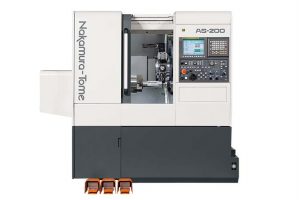
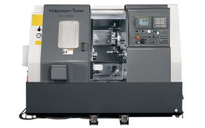
Specifications:
φ 2″ φ2.56 Capacity Max. turning diameter 11.9″ (300 mm) Max. turning length 19.7″ (500 mm) Distance between spindle nose (max/min) 30.7″ /11″ (780 mm/ 280 mm) with sub spindle (op.) Bar capacity 2″ 2 9/16″ Chuck size 8″ (215 mm) Axis travel Slide travel (X) 7″ (177.5 mm) Slide travel (Z) 21.7″ (550 mm) Slide travel (Y) ±1.6″ (41 mm)(op.) Slide Travel (B) 19.7″ (500 mm) (op) Rapid feed (X) 630 in/min (16 m/min) Rapid feed (Z) 1181 in/min (30 m/min) Rapid feed (B) 1181 in/min (30 m/min) (op) Rapid feed (Y) 236 in/min (6 m/min) (op) Spindle Spindle speed 4500 rpm 4500 rpm Spindle Speed Range Stepless Spindle Nose A2-6 Hole Through Draw Tube 2.5″ ( 65 mm) SUB SPINDLE (OP.) Spindle Speed 5000 rpm Spindle Speed Range Stepless Spindle Nose A2-5 Hole Through Draw Tube 2″ (52 mm) C-AXIS Least Input Increment 1E-3 degree Turret Number of Tool Stations 12 Rotary system/Number of driven-tool stations 12 MILLING TOOLS Spindle Speed 3600 rpm Number of Milling-Tool Stations 12 ROTATING TOOL Rotary System Individual Rotation Spindle Speed 3600 rpm Spindle Speed Range Stepless Number of Rotation Tool Station 12 DRIVE MOTOR POWER Main Spindle 20 HP Sub Spindle (op.) 15 ( op) HP Driven Tool Spindle 7.5 HP TAILSTOCK (OP.) Quill Diameter 3.2 (80) in (mm)Quill Taper Quill Taper MT-4 Rotating Center Quill Stroke 3.2″ (80 mm) General Machine weight 8378 lbs (3800 kg) -
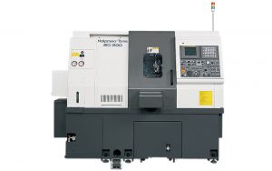
Specifications:
Capacity Swing Over Bed 15.8 (400) in (mm) Max Workpiece Swing Diameter 12.6 (320) in (mm) Max Turning Diameter 13.4 (340) in (mm) Distance Between Spindle Noses 31.5 in (mm) Max Turning Length 22.5 (570) in (mm) Bar Capacity 2.6 (65) in (mm) Bar Capacity Sub 1.7 (42) in (mm) Chuck size 8 (203) in (mm) Axis travel Slide travel (X) 9 (227.5) in (mm) Slide travel (Z) 23 (585) in (mm) Slide travel (Y) ±1.6 (41)(op.) in (mm) Slide Travel (B) Rapid feed (X) 945 (24) in/min (m/min) Rapid feed (Z) 1418 (36) in/min (m/min) Rapid feed (B) Rapid feed (Y) 236 (6)(op.) in/min (m/min) Spindle Spindle speed 4500 rpm Spindle Speed Range Stepless Spindle Nose A2-6 Hole Through Draw Tube 2.5 ( 65mm) in (mm) C-AXIS Least Input Increment 1E-3 degree Turret Number of Tool Stations 12 Rotary system/Number of driven-tool stations 24 MILLING TOOLS Spindle Speed 6000 rpm Number of Milling-Tool Stations 12 ROTATING TOOL Rotary System Individual Rotation Spindle Speed 6000 rpm Spindle Speed Range Stepless Number of Rotation Tool Station 12 DRIVE MOTOR POWER Main Spindle 20 HP Sub Spindle (op.) 10 HP Driven Tool Spindle 7.5 HP General Machine weight 11023 (5000) lbs (kg) -
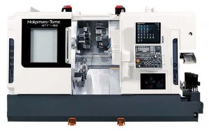
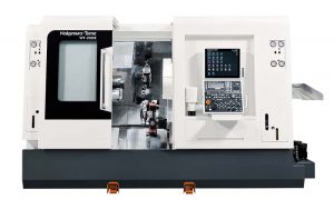
Specifications
φ 2″ φ 2.56″ Capacity Max. turning diameter 27″ Max. turning length 27″ Distance between spindle nose max. 38.2″ | min. 7.87″ Bar capacity 2″ 2.56″ Chuck size 6″ (165mm) Axis travel Slide travel X1/X2/X3 6.31″ Slide travel Z1/Z2/Z3/B 9.25″ | 9.25″ | 27″ Slide travel B 30.3″ Slide travel Y1/Y2/Y3 ± 1.76″ | ± 1.76″ | ± 1.37″ Left spindle Right spindleR Spindle speed 5,000min-1 4,500min-1 spindle motor L:R (min/cont.) 20/15hp : 15/10hp Upper turret Number of turrets 2 Spindle speed 6,000min-1 Driven motor power (min/cont.) 7.5/5hp Driven motor torque (min/cont.) 17.7/11.8 ft.lbs Type of turret head Dodecagonal Number of index positions 24 Rotary system Individual rotation Number of driven-tool stations 12 Lower turret Number of turrets 1 Spindle speed 6,000min-1 Driven motor power (min/cont.) 7.5/5 hp Driven motor torque 17.7/11.8hp Type of turret head Dodecagonal Number of index positions 24 Rotary system Individual rotation Number of driven-tool stations 12 General Floor space H 86″ L 150″ W 87″ Machine weight 10,000kg -
Specifications:
Capacity Φ 2″ Φ 2.56″ Φ 2.79″ Max. turning diameter 12st. 6.89″ – 23.15″ 7.88″ – 22.44″ / Max. turning length 15st. 7.48″ – 23.16″ 7.48″ – 22.44″ Distance between centers max. 32.28″ – min. 7.88″ Bar capacity 2″ 2.56″ 2.79″ Chuck size 6″ (165mm) Axis travel Slide travel X1/X2 12st. 5.9″ – 5.3″ 5.9″ – 5.55″ 15st. 5.7″ – 5.13″ Slide travel Z1/Z2 12st. 23.16″ – 22.75″ 22.44″ – 22″ 15st. 23.16″ – 22″ Slide travel B2 24.4″ Slide travel Y1/Y2 12st. ± 1.66″ | ±1.28″ 15st. ±1.22 | ±1.22″ Left and right spindle Spindle speed 6,000min-1 5,000min-1 4,500min-1 Spindle drive motor L/R 15/10hp 15/10hp (20/15hp op.) Upper turrets Number of turrets 1 Spindle speed 6,000min-1/8,000min-1(op. Dodecagonal) Driven motor 10/3hp (7.5/3hp op.) Type of turret head 12st. Dodecagonal/24 / Number of index positions 15st. Pentagonal/15 Rotary system 12st. Individual rotation/12 / Number of driven-tool stations 15st. Individual rotation/15 Lower turrets Number of turrets 1 Spindle speed 6,000min-1/8,000min-1(op. Dodecagonal) Driven motor 10/3hp (7.5/3hp op.) Type of turret head 12st. Dodecagonal/24 / Number of index positions 15st. Pentagonal/15 Rotary system 12st. Individual rotation/12 / Number of driven-tool stations 15st. Individual rotation/15 General Floor space (L×W×H) 135″ × 89″ × 76″ Machine weight 9,000kg -
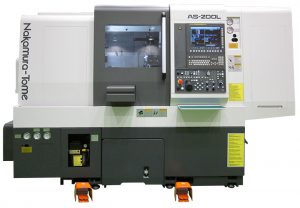
Specifications:
φ 2″ φ2.56 Capacity Max. turning diameter 11.9 (300) in (mm) Max. turning length 19.7 (500) in (mm) Distance between spindle nose max 30.7 (780) /min 11 (280) with sub spindle (op.) in (mm) Bar capacity 2″ 2 9/16″ Chuck size 8 (215) in (mm) Axis travel Slide travel (X) 7 (177.5) in (mm) Slide travel (Z) 21.7 (550) in (mm) Slide travel (Y) ±1.6 (41)(op.) in (mm) Slide Travel (B) 19.7 (500)(op.) in (mm) Rapid feed (X) 630 (16) in/min (m/min) Rapid feed (Z) 1181 (30) in/min (m/min) Rapid feed (B) 1181 (30)(op.) in/min (m/min) Rapid feed (Y) 236 (6)(op.) in/min (m/min) Spindle Spindle speed 4500 rpm 4500 rpm Spindle Speed Range Stepless Spindle Nose A2-6 Hole Through Draw Tube 2.5 ( 65mm) in (mm) SUB SPINDLE (OP.) Spindle Speed 5000 rpm Spindle Speed Range Stepless Spindle Nose A2-5 Hole Through Draw Tube 2 (52) in (mm) C-AXIS Least Input Increment 1E-3 degree Turret Number of Tool Stations 12 Rotary system/Number of driven-tool stations 12 MILLING TOOLS Spindle Speed 3600 rpm Number of Milling-Tool Stations 12 ROTATING TOOL Rotary System Individual Rotation Spindle Speed 3600 rpm Spindle Speed Range Stepless Number of Rotation Tool Station 12 DRIVE MOTOR POWER Main Spindle 20 HP Sub Spindle (op.) 15 ( op) HP Driven Tool Spindle 7.5 HP TAILSTOCK (OP.) Quill Diameter 3.2 (80) in (mm)Quill Taper Quill Taper MT-4 Rotating Center Quill Stroke 3.2 (80) in (mm General Machine weight 8378 (3800) lbs (kg) -
Specifications:
Capacity Max. turning diameter 17 (432) in (mm) Max. turning length 14.6 (370) in (mm) Bar capacity 2.6 (65) in (mm) Chuck size 8 (215) in (mm) Axis travel Slide travel (X) 10.0 (261) in (mm) Slide travel (Z) 14.4 (365) in (mm) Slide travel (Y) ±1.6 (41)(op.) in (mm) Slide Travel (B) 15.6 (395)(op.) in (mm) Rapid feed (X) 945 (24) in/min (m/min) Rapid feed (Z) 1418 (36) in/min (m/min) Rapid feed (B) 945 (24)(op.) in/min (m/min) Rapid feed (Y) 236 (6)(op.) in/min (m/min) Spindle Spindle speed 4500 rpm Spindle Speed Range Stepless Spindle Nose A2-6 Hole Through Draw Tube 2.5 ( 65mm) in (mm) SUB SPINDLE (OP.) Spindle Speed 5000 rpm Spindle Speed Range Stepless Spindle Nose A2-5 Hole Through Draw Tube 1.4 (35) in (mm) C-AXIS Least Input Increment 1E-3 degree Turret Number of Tool Stations 12 Rotary system/Number of driven-tool stations 12 MILLING TOOLS Spindle Speed 6000 rpm Number of Milling-Tool Stations 12 ROTATING TOOL Rotary System Individual Rotation Spindle Speed 6000 rpm Spindle Speed Range Stepless Number of Rotation Tool Station 12 DRIVE MOTOR POWER Main Spindle 15 HP Sub Spindle (op.) 7.5 HP Driven Tool Spindle 7.5 HP TAILSTOCK (OP.) Quill Diameter 3.2 (80) in (mm) Quill Taper MT-4 Rotating Center Quill Stroke 3.2 (80) in (mm General Machine weight 5952 (2700) lbs (kg) -
Specifications:
Capacity Max. turning diameter 16 (410) in (mm) Distance Between Spindles 31.5 (800) in (mm) Max. turning length 21 (530) in (mm) Bar capacity 2.6 (65) in (mm) Chuck size 8 (215) in (mm) Axis travel Slide travel (X) Slide travel (Z) 10.0 (261) in (mm) Slide travel (Y) ±1.6 (41)(op.) in (mm) Slide Travel (B) Rapid feed (X) 945 (24) in/min (m/min) Rapid feed (Z) 1418 (36) in/min (m/min) Rapid feed (B) 945 (24)(op.) in/min (m/min) Rapid feed (Y) 236 (6)(op.) in/min (m/min) Spindle Spindle speed 4500 rpm Spindle Speed Range Stepless Spindle Nose A2-6 Hole Through Draw Tube 2.6 (66) in (mm) SUB SPINDLE (OP.) Spindle Speed 6000 rpm Spindle Speed Range Stepless Spindle Nose A2-5 Hole Through Draw Tube 1.7 (43) in (mm) C-AXIS Least Input Increment 1E-3 degree Turret Number of Tool Stations 24 Rotary system/Number of driven-tool stations 24 MILLING TOOLS Spindle Speed 6000 rpm Number of Milling-Tool Stations 12 ROTATING TOOL Rotary System Individual Rotation Spindle Speed 6000 rpm Spindle Speed Range Stepless Number of Rotation Tool Station 12 DRIVE MOTOR POWER Main Spindle 15 HP Sub Spindle (op.) 7.5 HP Driven Tool Spindle 7.5 HP TAILSTOCK (OP.) Quill Diameter 3.2 (80) in (mm) Quill Taper MT-3 built-in center Quill Stroke 3.2 (80) in (mm General Machine weight 11023 (5000) lbs (kg) -
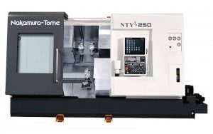
Specifications:
Capacity Max. turning diameter/Max. turning length 9.8″ / 21.8″ Distance between spindle nose Lφ2.6″ ,Rφ2″:max. 34.8″ / min. 10.4″
Lφ2.6″,Rφ2.6″(op.):max. 34.2″ / min. 9.8″Bar capacity L:2.6″ R:2″ R:2.6″op.) Chuck size 6″ (165mm) Axis travel Slide travel X1/X2 7.7″ / 7.7″ Slide travel Z1/Z2/B 23.6″ / 23.6″ / 24.4″ Slide travel Y upper turret ± 1.6″ Left spindle Right spindle Spindle speed L:φ2.6″ / 4,500min-1
R:φ2″ / 5,000min-1
R:φ2.6″(op.) / 4,500min-1Left spindle motor (max/cont.) 25/20hp
(op.45/35/30hp・20/15hp wide range)Right spindle motor (max/cont.) 15/10hp (op. 20/15hp・25/20hp) Upper turret Number of turrets 1 Spindle speed 6,000min-1 Type of turret head/Number of index positions Dodecagonal/24 Driven motor power (max/cont.) 7.5hp / 5hp Rotary system/Number of driven-tool stations Individual rotation/12 Lower turret Number of turrets 1 Spindle speed 6,000min-1 Type of turret head/Number of index positions Dodecagonal/24 Driven motor power (max/cont.) 7.5hp / 5hp Rotary system/Number of driven-tool stations Individual rotation/12 General Floor space (L×W×H) 160″ × 91″× 88″ Machine weight 8,700kg
Horizontal Turning Centers
CNC Lathe – Nakamura Tome Lineup
Machines Available in Pacific NortWest – USA
Horizontal Turning Centers are the most widely recognized. Vertical turning centers are regularly called a vertical turret lathe or VTL. With a horizontal turning center, the spindle is horizontally oriented, and tools are mounted out of the side of tool holder and cut across the work-piece